Zero. Starting from Horizontal Scaling
When scaling from a single machine to multiple machines, the first problem faced is how these machines coordinate work, i.e., how to schedule requests:
[caption id="attachment_2103" align="alignnone" width="625"]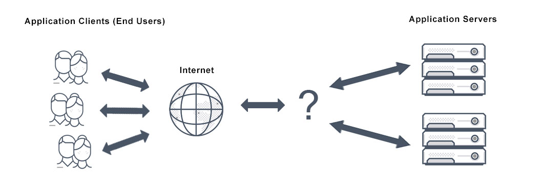 load balancer dispatcher[/caption]
P.S. For detailed information about horizontal and vertical scaling, see Scalability_System Design Notes 1
I. Load Balancer
The request scheduling mechanism under multiple servers is called load balancing, and the scheduler (Dispatcher) is the load balancer:

Its main function is to distribute client requests to various servers according to established strategies (such as random, round-robin):
The fundamental feature of a load balancer is to be able to distribute incoming requests over a number of backend servers in the cluster according to a scheduling algorithm.
Helpful for:
-
Preventing requests from reaching unavailable servers
-
Preventing resource overload
-
Eliminating single points of failure, improving availability
Additionally, can be used for:
-
SSL termination: Handle SSL connections, moving encryption/decryption work to the scheduling layer
-
Session persistence: Centrally handle sessions to avoid session state loss when switching servers
That is to say, in multi-machine scenarios, there must be a load balancer responsible for distributing/scheduling requests. So the next question is at which layer should the load balancing mechanism be implemented
II. Implementation Approaches
Consider the communication process of an HTTP request from client to server, which can be simply divided into 3 stages:
-
Departure: Client sends request
-
In transit: Request transmitted through network
-
Arrival: Server receives request
To distribute/schedule requests is to find ways (according to established strategies) to change the request's destination, so there are at least 3 approaches:
-
Before departure: Determine the final destination before the request is transmitted through the network, such as DNS load balancing, client-side load balancing
-
During transit: Change destination at certain points during network transmission, such as layer 4 load balancing
-
After arrival: Perform secondary distribution after the request reaches the server, such as layer 7 load balancing
III. DNS Load Balancing
When a client wants to initiate a request to a server, it first needs to know the server's IP address, queried through DNS:
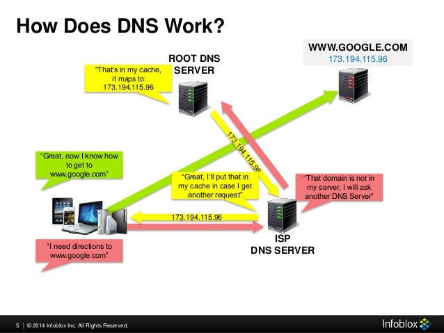
DNS maintains the mapping relationship between domain names and IP addresses, so load balancing strategies can be implemented here, pointing requests to target servers (IP addresses), for example:
-
Round-robin distribution: Add a series of A records, pointing the same domain name to multiple different IP addresses, called round-robin DNS
-
Random distribution: Use DNS services supporting multi-value answer routing policies
Simple and easy to use, but defects are also obvious:
-
Reliability not guaranteed: DNS doesn't check server availability, even if the target server is down or inaccessible, it still returns its IP address
-
Updates not timely: DNS resolution results are often cached at multiple levels, record updates cannot take effect immediately
P.S. For more information about DNS load balancing, see What Is DNS Load Balancing?
IV. Client-Side Load Balancing
Similarly, implementing the server IP address selection mechanism on the client side is called client-side load balancing
The client selects the target server's IP address itself (no longer through DNS query):
[caption id="attachment_2105" align="alignnone" width="445"]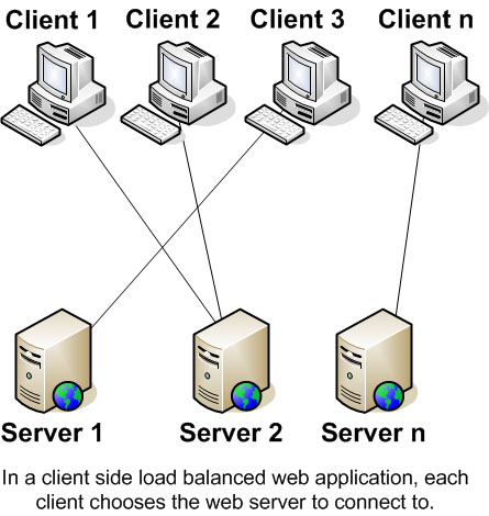 client-side load balancing[/caption]
For example, providing a server IP list to the client, the client randomly selects an IP before initiating a request, achieving the purpose of random distribution
Compared to DNS load balancing, the client doesn't have caching issues and can perform finer-grained control, such as checking service availability and selecting available IP addresses from them
V. OSI Seven-Layer Model
After the request is sent from the client, it's then transmitted through the network
OSI (Open System Interconnect) reference model divides network communication into 7 abstract layers:

From bottom to top, in order:
-
Physical Layer (Layer 1): Transmits raw bit streams through physical media, i.e., physical signals (Symbol)
-
Data Link Layer (Layer 2): Provides reliable node-to-node data frame transmission mechanism, specific work includes MAC addressing
-
Network Layer (Layer 3): Determines the physical path that packet transmission will take, supports IP, ARP and other protocols, specific work includes IP addressing, routing and flow control
-
Transport Layer (Layer 4): Provides reliable datagram transmission mechanism, supports TCP, UDP and other transport protocols, specific work includes
-
Session Layer (Layer 5): Responsible for managing sessions to support continuous information exchange through multiple transmissions
-
Presentation Layer (Layer 6): Translates data from network services into formats usable by the application layer, specific work includes character encoding conversion, data compression, encryption/decryption, etc.
-
Application Layer (Layer 7): Human-machine interaction layer providing high-level APIs, applications can access network services through this layer, such as resource sharing, remote file access, etc.
Among them, Layer 1 is raw data, Layer 2 determines the target machine's MAC address, Layer 3 determines the endpoint's IP address and the specific route taken. By Layer 4, the target port number is determined according to the transport protocol. Layers 5~7 don't care about the endpoint because IP address + MAC address + port number have uniquely determined the target application
That is to say, an HTTP request must pass through these layers to reach the target server. So, theoretically, there's an opportunity to change the endpoint and implement load balancing at any layer from 2~7
But common load balancing mechanisms are mostly implemented at layer 4 and layer 7. Why is that?
VI. Layer 2, Layer 3 Load Balancing
-
Layer 2 load balancing: Distributes based on source/destination MAC addresses, such as mapping virtual MAC addresses to actual MAC addresses according to established strategies
-
Layer 3 load balancing: Distributes based on source/destination IP addresses and Layer 2 information, such as resolving Virtual IP addresses
The closer to the lower layers, the less information available for distribution decisions, so Layer 2 load balancing has limited practical use. Common ones are only redundancy gateway protocols (such as GLBP, VRRP) and link aggregation (Link aggregation, also called etherchannel), etc. See How is load balancing achieved with layer 2 devices?
VII. Layer 4 Load Balancing
Layer 4 load balancing distributes requests based on transport layer (Layer 4) information, including source/destination IP addresses and port numbers in the packet header, but doesn't consider packet content:
Layer 4 load balancing uses information defined at the networking transport layer (Layer 4) as the basis for deciding how to distribute client requests across a group of servers. For Internet traffic specifically, a Layer 4 load balancer bases the load-balancing decision on the source and destination IP addresses and ports recorded in the packet header, without considering the contents of the packet.
The client initiates a request using the load balancer's IP address as the target IP address. After receiving the request, the Layer 4 load balancer performs NAT conversion on the packet, changing the target IP address to the actual server's address. Before forwarding the server response to the client, the load balancer changes the source IP address back to its own IP address. Similarly, source/destination port numbers in the packet are modified in this way
P.S. Layer 4 load balancers are usually dedicated hardware devices, NAT operations may be completed by dedicated chips
Compared to more complex Layer 7 load balancing, Layer 4 load balancing requires less computation, but under current hardware conditions, the performance advantage brought by this is no longer important
P.S. Strictly speaking, Layer 4 load balancing should be called Layer 3/4 load balancing, because it combines Layer 3 IP address and Layer 4 port number information
VIII. Layer 7 Load Balancing
Layer 7 load balancing distributes based on application layer protocol information (such as HTTP headers) and packet content information, including URL, data type, Cookie information, etc.:
Layer 7 load balancers base their routing decisions on various characteristics of the HTTP header and on the actual contents of the message, such as the URL, the type of data (text, video, graphics), or information in a cookie.
Compared to Layer 4 load balancing, Layer 7 load balancers can read request and response content. Although more computation is required, it's not necessarily worse in performance than Layer 4 load balancing, because having more comprehensive context information, smarter global decisions can be made on this basis (such as eliminating slow connections, redirecting timeout requests), and content can even be optimized (such as compression), thereby improving performance
P.S. Strictly speaking, Layer 7 load balancing should be called Layer 5~7 load balancing, because it combines information from layers 5~7 in the OSI model:
[caption id="attachment_2110" align="alignnone" width="800"]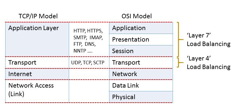 TCP/IP model and OSI model[/caption]
No comments yet. Be the first to share your thoughts.